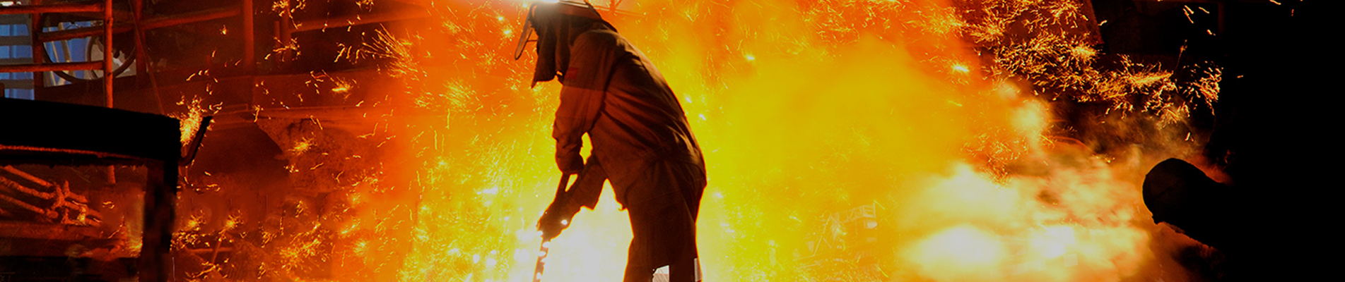
Wybór pomiędzyzłącze dylatacyjne z tkaninyimetalowy dylatatorNie chodzi tylko o to, który produkt jest mocniejszy lub który materiał wytrzyma najwyższą temperaturę. Prawidłowy wybór zależy od sposobu poruszania się systemu, ciśnienia, pod jakim pracuje, rodzaju przepływającego przez niego medium, rozmiaru kanału lub rury oraz obciążenia, jakie można przenieść na podłączone urządzenia.
Ogólnie rzecz biorąc, kompensatory materiałowe są bardzo skuteczne w dużych systemach kanałów niskociśnieniowych, przesyłających gorące powietrze, gazy spalinowe lub spaliny, natomiast w przypadku rurociągów ciśnieniowych i systemów procesowych, w których kluczowe znaczenie mają ograniczenie ciśnienia i wytrzymałość mechaniczna, powszechnie wybiera się miechy metalowe.
Poniższe porównanie wyjaśnia, gdzie każda konstrukcja sprawdza się najlepiej i jakie czynniki należy wziąć pod uwagę przed określeniem złącza dylatacyjnego.
Szybka decyzja:
Wybierzzłącze dylatacyjne z tkaninygdy zastosowanie obejmuje duże kanały, niskie ciśnienie, znaczny ruch boczny lub mieszany, wibracje, gorące gazy lub ograniczone dopuszczalne obciążenia reakcji.
Wybierzmetalowy dylatatorgdy zastosowanie obejmuje rurociągi pod ciśnieniem, parę, ciecze, większe obciążenia mechaniczne lub system specjalnie zaprojektowany wokół mieszków metalowych.
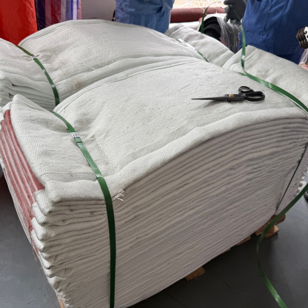
| Czynnik selekcji | Złącze dylatacyjne materiałowe | Metalowe złącze kompensacyjne |
|---|---|---|
| Typowa usługa | Kanały przemysłowe i media gazowe | Rurociągi, zbiorniki i systemy procesowe |
| Zdolność ciśnieniowa | Głównie zastosowania niskociśnieniowe | Można go zaprojektować do znacznie wyższego ciśnienia |
| Duże rozmiary kanałów | Bardzo odpowiedni | Możliwe, ale zwykle bardziej złożone mechanicznie |
| Ruch osiowy | Doskonały, jeśli jest odpowiednio zaprojektowany | Doskonały z odpowiednią geometrią miecha |
| Ruch boczny | Wysoka zdolność ruchu w kompaktowych układach | Zwykle wymaga odpowiedniej konfiguracji miecha |
| Ruch kątowy | Możliwość łączenia ruchów | Dostępne z konfiguracją inżynieryjną |
| Izolacja wibracji | Bardzo dobra elastyczność | Zależne od aplikacji |
| Siła sprężyny | Generalnie niski | Miechy generują mierzalne siły sprężyny |
| System materiałowy | Tkaniny kompozytowe, membrany i izolacje | Mieszki ze stopów metali |
| Media powszechne | Gorące powietrze, gazy spalinowe, spaliny, gazy procesowe | Para, ciecze, gazy i płyny procesowe |
| Typowa geometria | Okrągłe, prostokątne i duże niestandardowe kształty | Głównie okrągłe, ale dostępne są również wersje o prostokątnych kształtach |
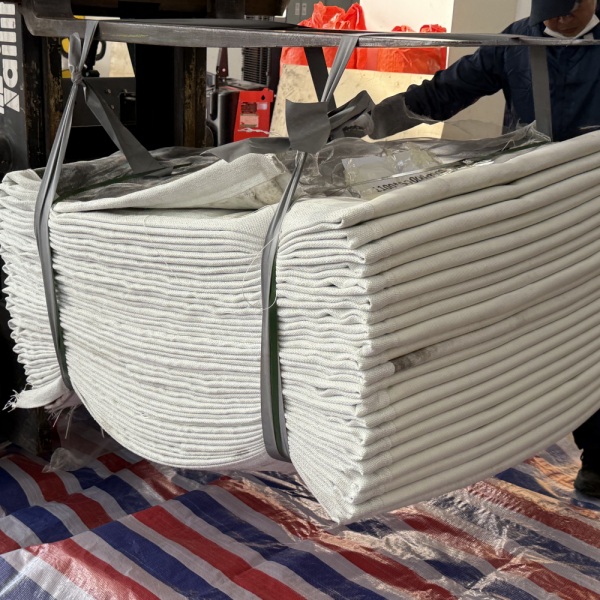
Jednym z najprostszych sposobów rozpoczęcia procesu selekcji jest ustalenie, czy złącze kompensacyjne będzie instalowane w dużym kanale przemysłowym, czy w systemie rurociągów ciśnieniowych.
Azłącze kompensacyjne z tkaniny niemetalowejSzczególnie dobrze nadaje się do dużych kanałów powietrznych i gazowych. Systemy te są często spotykane w elektrowniach, cementowniach, hutach stali, piecach przemysłowych, systemach odpylania, urządzeniach do spalania oraz instalacjach wydechowych.
Medium procesowe jest zazwyczaj gazowe, a ciśnienie jest często stosunkowo niskie w porównaniu z rurociągami procesowymi pod ciśnieniem.
Kompensator metalowy wykorzystuje cienką, formowaną, metalową konstrukcję, aby zapewnić elastyczność przy jednoczesnym zachowaniu stabilności ciśnienia. Mieszki metalowe są szeroko stosowane w instalacjach parowych, rurociągach procesowych, petrochemicznych, chemicznych i innych instalacjach inżynieryjnych, w których ciśnienie jest głównym wymogiem projektowym.
Różnica w środowisku aplikacji wyjaśnia wiele różnic w wydajności między tymi dwiema technologiami.
Ciśnienie jest często pierwszym czynnikiem odróżniającym kompensator tkaninowy od mieszka metalowego.
Złącza tkaninowe przeznaczone są przede wszystkim do kanałów niskociśnieniowych. Ich elastyczny element składa się z powlekanych tkanin, warstw wzmacniających, membran uszczelniających i izolacji, a nie z metalowych mieszków pod ciśnieniem.
Można je powszechnie znaleźć w:
Mieszek metalowy można zaprojektować tak, aby wytrzymywał znacznie większe ciśnienie wewnętrzne. Jego karbowana metalowa ścianka zapewnia zarówno elastyczność, jak i ograniczanie ciśnienia.
Dzięki temu metalowe złącza kompensacyjne nadają się do zastosowań takich jak:
Zasada wyboru:Jeśli konieczne jest ograniczenie znacznego ciśnienia w układzie, zazwyczaj w pierwszej kolejności należy rozważyć zastosowanie mieszków metalowych. Kompensatorów tkaninowych nie należy traktować jako bezpośredniego zamiennika miechów metalowych o wytrzymałości na ciśnienie.
Ruch to cecha, która sprawia, że wzory tkanin stają się szczególnie atrakcyjne.
Pas tkaninowy może odkształcać się na stosunkowo dużym obszarze. Pozwala to na kompensację znacznych przemieszczeń osiowych, poprzecznych i kątowych bez konieczności stosowania wielu formowanych metalowych splotów.
W przypadku dużych systemów kanałów, w których rozszerzalność cieplna występuje w więcej niż jednym kierunku, może to znacznie uprościć rozmieszczenie złączy kompensacyjnych.
Mieszki metalowe również mogą być dostosowane do tego typu ruchów, ale ich konfiguracja musi być specjalnie zaprojektowana pod kątem tych ruchów.
For example, larger lateral displacement may require a universal metallic expansion joint with multiple bellows and a center pipe rather than a single bellows element.
Therefore, when large lateral or combined movement is required in a low-pressure duct, afabric expansion jointis often the more practical design.
This is an important engineering difference that is often overlooked during purchasing.
A metallic bellows behaves like a mechanical spring. When it is compressed, extended or laterally displaced, it generates reaction forces that must be considered in the piping design.
These forces may influence:
Fabric expansion joints generally produce much lower spring forces because the flexible textile element is considerably softer than formed metal bellows.
For large duct systems connected to fans, furnaces or lightweight structural components, reducing these reaction loads can be a major advantage.
Fans, blowers, turbines and other rotating equipment can transmit vibration into connected ductwork.
A flexible fabric connector can help isolate some of this vibration because the textile belt does not create the same rigid mechanical path as solid ductwork.
This makes fabric expansion joints especially useful around:
Metal expansion joints can also accommodate vibration, but the movement amplitude, frequency and expected cycle life must be considered carefully in the bellows design.
For high-cycle vibration, neither product should be selected solely from a general product specification. Actual vibration data should be supplied to the manufacturer.
Large rectangular ductwork strongly favors fabric construction in many industrial systems.
Consider an exhaust duct measuring several meters across. Producing a metallic flexible element for such a large cross-section requires substantial metal fabrication and careful control of corner stresses.
A rectangular fabric joint can use a flexible belt installed around the perimeter of the duct, making very large dimensions more practical.
This is whyrectangular fabric expansion jointsare frequently seen in:
For these applications, size alone can significantly influence the final choice.
It is incorrect to assume that metal is always better at high temperature or that fabric automatically has a lower usable process temperature.
The two systems manage temperature differently.
Metallic bellows temperature capability is determined primarily by the selected alloy, design pressure, material strength at temperature and expected fatigue life.
Stainless steels and nickel-based alloys can be selected for elevated-temperature service.
A high-temperature fabric expansion joint may use several thermal layers rather than exposing one flexible membrane directly to the process gas.
A typical construction may include:
The insulation package can reduce the temperature reaching the external sealing materials.
Therefore, ahigh temperature fabric expansion jointshould be selected based on the full temperature gradient through the joint, not simply on the temperature rating of one fabric.
Hot flue gas and exhaust systems are among the most common applications for non-metallic designs.
These installations often combine:
That combination closely matches the strengths of fabric expansion joints.
Typical installations include:
For customized designs, BSTFLEX manufacturesNon Metallic Fabric Expansion Jointsfor industrial ducting, hot-air, flue-gas and exhaust applications.
Corrosion resistance cannot be judged simply by comparing “fabric” with “metal.”
The actual materials must be compared.
A metallic expansion joint may use corrosion-resistant stainless steel or nickel alloy when aggressive media are present.
A fabric expansion joint may use chemical-resistant barrier layers such as PTFE-coated textiles or other compatible membrane systems.
Selection should consider:
Condensation is particularly important in flue-gas systems because chemical attack may become more severe when corrosive gases condense on cooler joint surfaces.
Neither fabric nor metallic bellows should necessarily be exposed directly to severe turbulent flow or abrasive particles without protection.
A fabric joint may use:
A metallic bellows may also require an internal liner to prevent erosion, turbulent excitation or direct impingement on the convolutions.
This means gas velocity, dust loading and flow direction should always be included in the expansion joint specification.
Available space can strongly affect the decision.
A fabric joint can often absorb considerable lateral movement within a relatively short flexible span.
Metallic systems can also accommodate large displacement, but may require more complex arrangements such as universal joints, hinged joints or gimbal configurations depending on movement direction.
However, there are also piping layouts where a compact metallic bellows is the more appropriate design.
Installation space should therefore be considered together with pressure and movement rather than as an isolated factor.
Fabric flexible elements are generally lighter than comparable large metallic assemblies.
This difference becomes increasingly important as duct dimensions increase.
Lower component weight can reduce loads during:
In very large rectangular duct systems, this can be an important practical advantage.
Fabric expansion joints are often designed with replaceable flexible belts.
If the surrounding steel frames remain serviceable, maintenance may involve replacing the flexible element rather than removing the complete assembly.
This can be useful in large duct installations where removing welded steel frames would create significant shutdown work.
Metal expansion joints generally require replacement or repair of the metallic bellows assembly when the bellows itself becomes damaged.
The actual maintenance cost depends on system design, accessibility, joint size and failure mode.
There is no meaningful universal statement such as “metal lasts longer than fabric.”
Service life depends on whether the joint was correctly designed for the application.
A fabric joint can fail prematurely because of:
A metal bellows can fail because of:
Correct engineering matters more than simply choosing one material category over another.
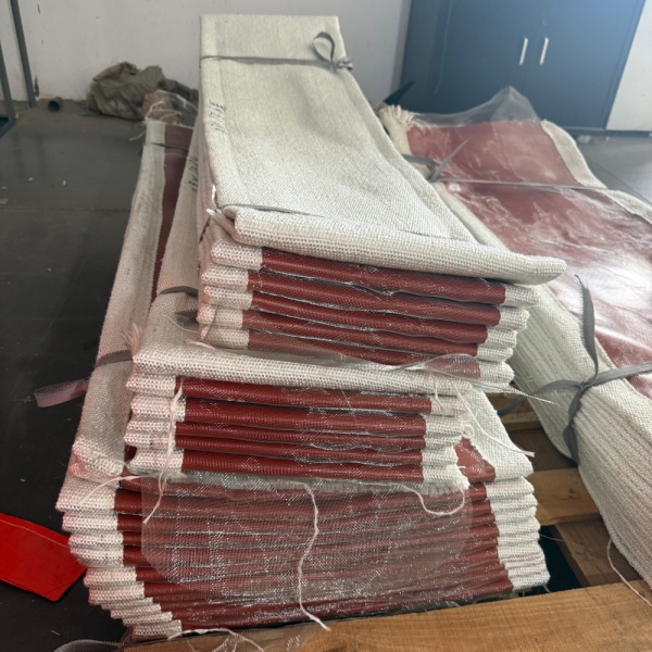
| Application | Usually Preferred | Reason |
|---|---|---|
| Large Low-Pressure Flue Gas Duct | Fabric Expansion Joint | Large size, flexibility and multidirectional movement |
| High-Pressure Steam Pipe | Metal Expansion Joint | Pressure containment requirement |
| Large Rectangular Exhaust Duct | Fabric Expansion Joint | Practical for large custom cross-sections |
| Fan Connection | Fabric Expansion Joint | Low reaction forces and vibration isolation |
| Pressurized Chemical Pipeline | Metal Expansion Joint | Pressure and mechanical requirements |
| Cement Kiln Exhaust Duct | Fabric Expansion Joint | Hot gas, large duct and substantial movement |
| Process Piping | Metal Expansion Joint | Engineered for piping pressure and code requirements |
| Large Boiler Flue Duct | Fabric Expansion Joint | Low-pressure hot-gas application |
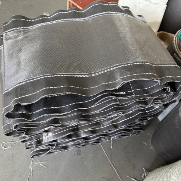
Afabric expansion jointshould be seriously considered when most of the following conditions are present:
This is the typical application envelope for anon metallic expansion joint.
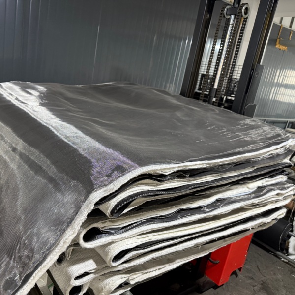
A metallic expansion joint should normally be evaluated first when:
Metallic bellows are engineered pressure-containing components and should be designed around system pressure, temperature, movement, material, fatigue life and piping loads.
Instead of asking, “Which expansion joint is better?” engineers should ask, “Which expansion joint architecture matches this system?”
Use the following sequence.
Is it a large duct or pressurized pipe?
Specify normal pressure, design pressure and whether the system operates under positive or negative pressure.
Provide both continuous operating temperature and maximum excursion temperature.
List axial compression, axial extension, lateral displacement and angular movement individually.
Specify hot air, exhaust gas, flue gas, steam, liquid or process chemical.
Include gas velocity, dust loading, abrasive particles and turbulence.
Determine how much reaction force can safely be transferred to fans, duct supports, equipment nozzles and anchors.
Confirm shape, dimensions, flange arrangement and available face-to-face installation length.
Consider a large rectangular flue-gas duct installed downstream of industrial combustion equipment.
The system has:
In this situation, a fabric expansion joint is often an efficient choice because it can combine large cross-section capability, multidirectional flexibility and low reaction forces.
Now consider a high-pressure steam line operating at elevated temperature.
Although thermal movement still exists, the system requires reliable pressure containment. A metallic bellows engineered for the piping pressure, temperature and movement is generally the appropriate technology.
These examples demonstrate why the operating system must determine the expansion joint type.
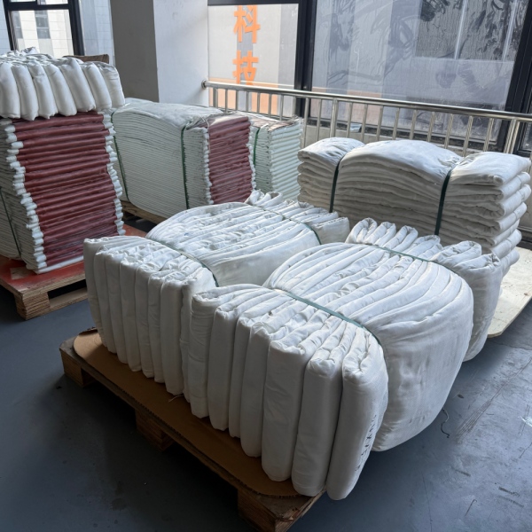
For either metallic or fabric designs, the quality of the engineering recommendation depends heavily on the information supplied.
For a custom fabric joint, BSTFLEX recommends providing:
BSTFLEX manufactures custom non-metallic expansion joints for industrial hot-air, exhaust and flue-gas ducting systems.
Depending on operating conditions, flexible constructions can incorporate technical fabrics, coated fiberglass, PTFE-based sealing layers, high-temperature insulation and protective components.
Round, rectangular and application-specific configurations can be manufactured according to customer drawings and operating data.
See theBSTFLEX Złącze kompensacyjne z tkaniny niemetalowejw celu uzyskania niestandardowych opcji produkcji.
Jeżeli w Twoim zastosowaniu wykorzystywany jest duży kanał przemysłowy przesyłający gorące powietrze, spaliny lub gazy spalinowe, prześlij do BSTFLEX rysunek i warunki eksploatacji w celu oceny.
Należy uwzględnić wymiary kanału, temperaturę, ciśnienie, media, ruch osiowy, ruch boczny, długość płaszczyzny czołowej oraz ilość.
Poproś o wycenę niestandardowego złącza kompensacyjnego z tkaniny

 English
 français
 Deutsch
 русский
 italiano
 español
 português
 Nederlands
 العربية
 日本語
日本語 한국의
한국의 Türkçe
 Tiếng Việt
 slovenský
 Indonesia