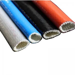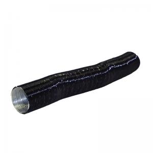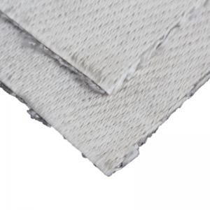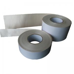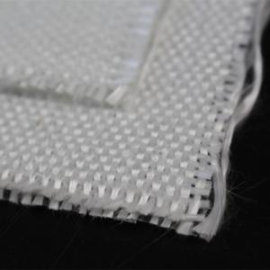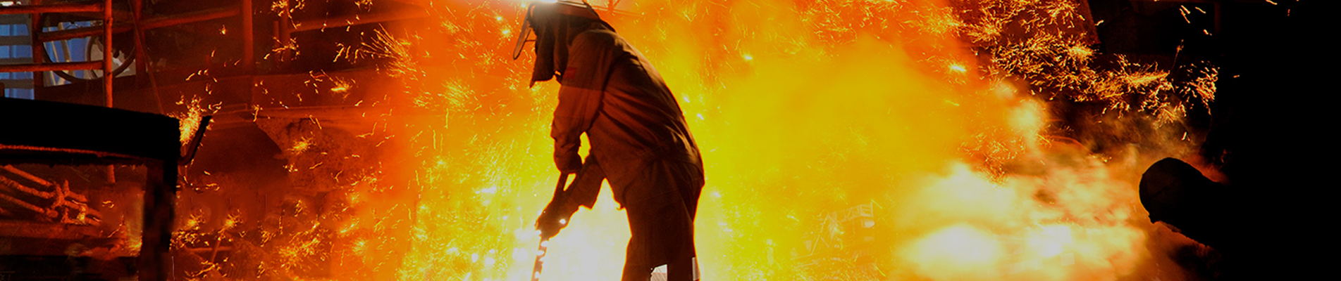
Azłącze dylatacyjne z tkaninyto elastyczne połączenie montowane w kanałach przemysłowych w celu pochłaniania ruchów między sekcjami urządzeń lub kanałów. Zamiast wymuszać rozszerzalność cieplną, drgania lub zmiany ustawienia sztywnych konstrukcji stalowych, elastyczny odcinek odkształca się podczas ruchu systemu.
Kompensatory tkaninowe są powszechnie stosowane w systemach transportu gorącego powietrza, spalin, gazów spalinowych i innych gazowych mediów procesowych. Ich elastyczny element może składać się z tkanych tkanin technicznych, tkanin powlekanych, membran uszczelniających, warstw wzmacniających oraz izolacji termicznej dobieranej do rzeczywistych warunków pracy.
Ponieważ elastyczny element nie jest metalowy, ten typ połączenia jest również powszechnie nazywanyzłącze kompensacyjne niemetaloweLubzłącze kompensacyjne z tkaniny niemetalowej.
W przypadku niestandardowych projektów przemysłowych zapoznaj się zBSTFLEX Złącze kompensacyjne z tkaniny niemetalowej.
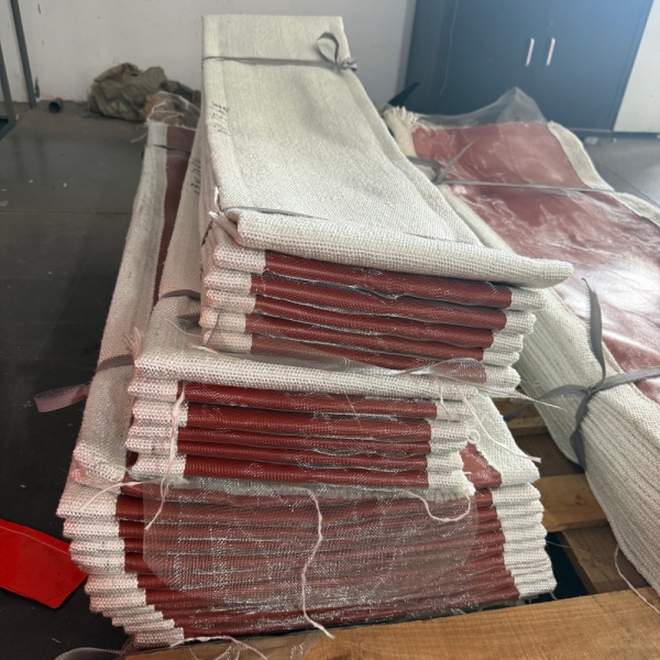
Kompensator tkaninowy to specjalnie zaprojektowany, elastyczny element umieszczony między dwoma stosunkowo sztywnymi częściami systemu kanałów. Jego celem jest umożliwienie kontrolowanego ruchu przy jednoczesnym zachowaniu wymaganego połączenia między tymi sekcjami.
Kanały przemysłowe rzadko zachowują swoje wymiary podczas eksploatacji. Gdy piec, kocioł, układ wydechowy lub kanał procesowy się nagrzewa, otaczająca go metalowa konstrukcja rozszerza się. Po ostygnięciu ponownie się kurczy. Wentylatory i urządzenia obrotowe mogą również wprowadzać drgania, a tolerancje montażowe mogą powodować niewielkie przesunięcia między sąsiednimi elementami.
Jeżeli ruchy te są przenoszone bezpośrednio przez sztywne kanały, mogą powodować dodatkowe obciążenia dla:
Połączenie tkanin tworzy elastyczną strefę, w której może odbywać się część ruchu, bez konieczności, aby cała konstrukcja kanału zachowywała się jak sztywny zespół.
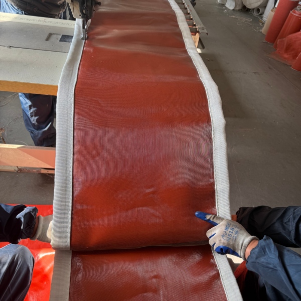
Terminzłącze kompensacyjne niemetaloweopisuje element elastyczny, a nie każdy komponent kompletnego zespołu.
Metalowe ramy, listwy zaciskowe, tuleje lub inne elementy konstrukcyjne mogą być nadal stosowane wokół stawu. Jednak sekcja, która wykonuje główny ruch giętki, jest wykonana z tkaniny, elastomeru, powlekanego materiału tekstylnego, laminowanej membrany lub kombinacji tych materiałów, a nie z formowanego metalowego mieszka.
To rozróżnienie jest istotne, ponieważ złącza kompensacyjne materiałowe i metalowe zachowują się odmiennie.
Metalowy mieszek kompensuje ruch poprzez wyginanie metalowych zwojów. Kompensator tkaninowy wykorzystuje elastyczność pasa tekstylnego lub kompozytowego, aby zmieniać kształt podczas ruchu kanału.
W przypadku dużych kanałów przemysłowych, zwłaszcza tych przesyłających media gazowe pod stosunkowo niskim ciśnieniem, konstrukcja ta zapewnia znaczną swobodę ruchu przy zachowaniu kompaktowej przestrzeni instalacyjnej.
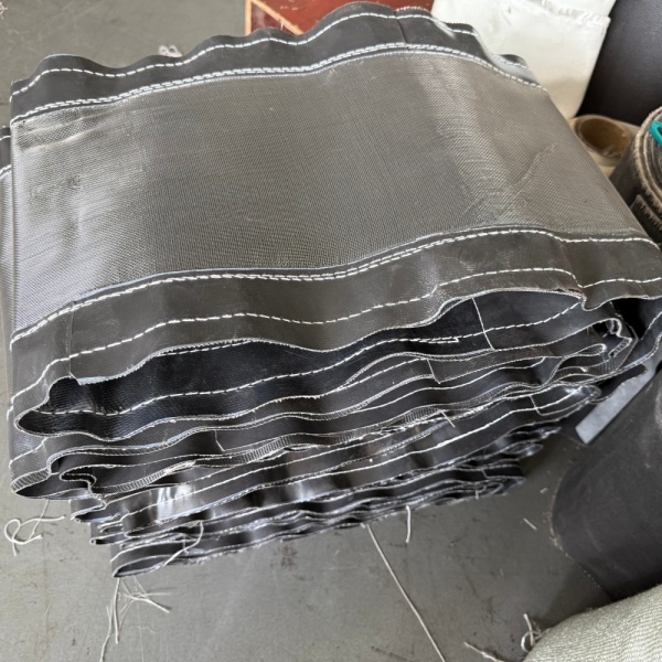
Podstawowa zasada działania jest prosta.
Wyobraź sobie dwa odcinki przewodu wentylacyjnego rozdzielone kontrolowaną szczeliną. Elastyczny element z tkaniny wypełnia tę szczelinę i jest solidnie przymocowany na obwodzie każdego odcinka przewodu.
Gdy kanał się nagrzewa i rozszerza, odległość lub wyrównanie między dwoma sekcjami ulega zmianie. Zamiast opierać się temu ruchowi, jak miałoby to miejsce w przypadku sztywnego połączenia, elastyczny pas zmienia kształt.
W zależności od konstrukcji staw może reagować na różne rodzaje ruchu.
Do ściskania osiowego dochodzi, gdy odległość między dwoma odcinkami kanału zmniejsza się wzdłuż linii środkowej.
Dzieje się tak często, gdy rozszerzalność cieplna powoduje, że jeden odcinek kanału przesuwa się w kierunku drugiego. Elastyczna rozpiętość ulega kontrolowanemu ściskaniu lub fałdowaniu, aby dostosować się do skrócenia odległości.
Wydłużenie osiowe to stan odwrotny. Odległość między sekcjami łączącymi zwiększa się wzdłuż osi podłużnej.
Element tkaniny musi mieć wystarczającą dostępną geometrię, aby móc się rozciągać, ale nie nadmiernie.
Ruch boczny występuje, gdy jedno połączenie kanału przesuwa się na bok względem drugiego.
Jest to szczególnie ważne w przypadku dużych systemów kanałów, w których ruch urządzeń, rozszerzalność cieplna w innym kierunku lub geometria instalacji powodują przesunięcie, a nie proste ściśnięcie lub wydłużenie.
Ruch kątowy występuje wtedy, gdy dwie łączące się powierzchnie nie są już równoległe.
Elastyczny pas odkształca się nierównomiernie na swoim obwodzie, co powoduje, że jedna jego część ulega ściśnięciu, a druga rozciągnięciu.
Rzeczywiste systemy przemysłowe nie zawsze poruszają się tylko w jednym kierunku. Przemieszczenia osiowe, boczne i kątowe mogą występować jednocześnie.
To jest jeden z powodówzłącze kompensacyjne kanału tkaninowegojest szczególnie przydatny w przypadku złożonych układów kanałów. Geometrię połączenia można zaprojektować w oparciu o oczekiwaną kombinację ruchów, zamiast traktować każde przemieszczenie oddzielnie.
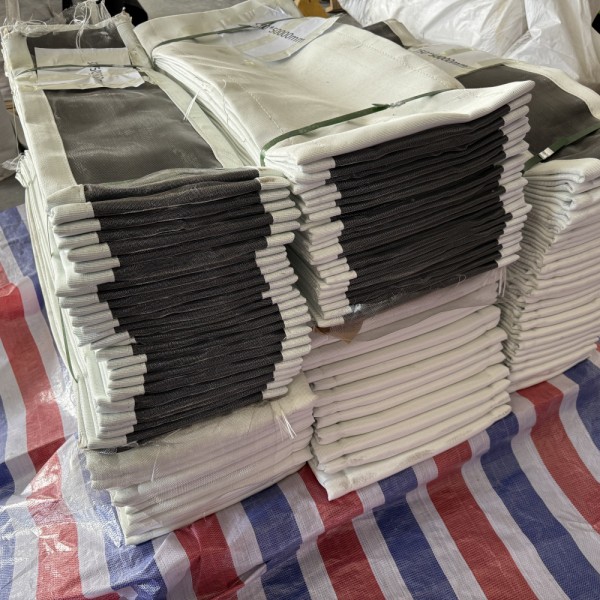
Rozszerzalność cieplna jest najbardziej znanym powodem instalowania złączy kompensacyjnych, ale nie jest to jedyny powód.
Całkowite zapotrzebowanie na ruch może wynikać z kilku warunków operacyjnych.
| Przyczyna | Co dzieje się w systemie | Rola złącza dylatacyjnego |
|---|---|---|
| Rozszerzalność cieplna | Kanały metalowe rozszerzają się wraz ze wzrostem temperatury | Umożliwia kontrolowany ruch wymiarowy |
| Skurcz termiczny | Kontrakty kanałów podczas wyłączania lub chłodzenia | Allows the system to return toward its cold position |
| Fan Vibration | Mechanical vibration is transferred from rotating equipment | Provides a flexible connection between equipment and ducting |
| Misalignment | Connecting duct faces may not be perfectly aligned | Can accommodate specified offsets within the joint design |
| Structural Movement | Supports or equipment may move relative to each other | Provides a controlled flexible section |
| Operating Cycles | Repeated heating and cooling creates cyclic movement | Accommodates repeated dimensional changes when correctly designed |
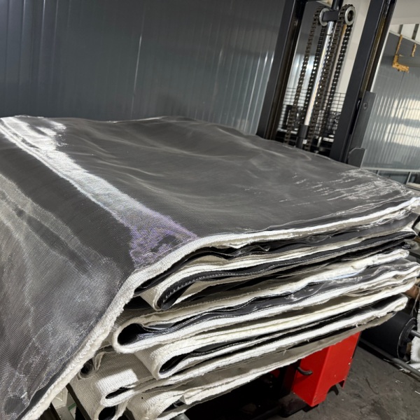
A fabric expansion joint should not be viewed simply as a piece of cloth connecting two ducts.
The flexible section is an engineered material system. Depending on service conditions, it may use a single flexible layer or several different layers, each selected for a specific function.
The outer layer forms part of the flexible envelope and may also provide resistance to weathering, environmental exposure or external mechanical conditions.
This layer helps contain the process gas. Its material must be compatible with the expected temperature, gas composition, moisture and chemical exposure.
Reinforcement provides mechanical support and dimensional stability to the flexible element. Fiberglass and other technical textile constructions are commonly considered depending on temperature and mechanical requirements.
High gas temperature does not necessarily mean every layer of an expansion joint should be exposed directly to that temperature.
An insulation package can reduce heat transfer from the process side toward temperature-sensitive sealing or outer layers.
Hot gas velocity, ash, dust or abrasive particles can damage an unprotected flexible surface. Some systems therefore require an internal liner, baffle or other protection to shield the joint from direct gas flow and particulate impact.
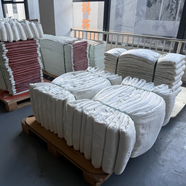
One material rarely provides every property required by a severe industrial application.
For example, a material with excellent temperature resistance may not provide the best gas sealing. A highly flexible sealing material may require reinforcement. A chemically resistant membrane may need insulation to keep its operating temperature within an acceptable range.
As a result, manyfabric expansion jointsuse a combination of materials rather than one fabric performing every function.
Typical material families include:
BSTFLEX also manufactures a broad range ofhigh temperature fabrics, allowing material construction to be evaluated according to thermal, chemical and mechanical requirements.
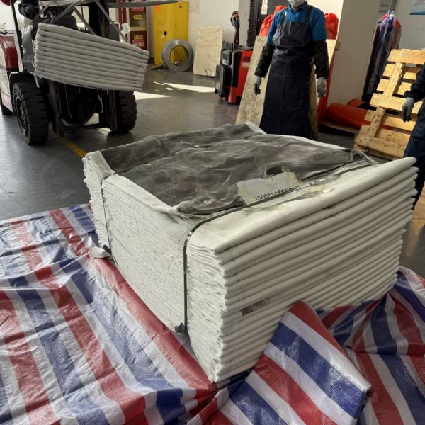
Fabric joints are mainly associated with industrial gas-handling and ducting systems rather than conventional high-pressure liquid piping.
Typical applications include the following.
Boilers, furnaces and combustion equipment can generate hot flue gases that must travel through large duct networks. These ducts experience significant dimensional change between ambient and operating temperatures.
Exhaust ducts connected to engines, industrial furnaces, thermal processing equipment or pollution-control systems may require movement compensation between hot equipment and downstream ducting.
Power plants use large gas-handling systems around boilers, fans, air-handling equipment and emission-control installations. Thermal growth and vibration can occur at multiple connection points.
Cement production combines heat, large duct dimensions, dust and continuous process operation. Flexible expansion sections may be required around kiln-related systems, fans and process ducts.
High-temperature furnaces, hot-air systems and exhaust ducts in steel and metal-processing plants can generate significant thermal movement.
Placing a flexible connection between rotating equipment and rigid ducting can help prevent all equipment movement from being transmitted directly into the surrounding duct structure.
Large ducting systems used with filtration, scrubber, flue-gas treatment and other air-pollution-control equipment often need flexible connections between process components.
Both products are intended to manage movement, but they should not be considered interchangeable simply because they share the term “expansion joint.”
| Characteristic | Fabric Expansion Joint | Metallic Bellows |
|---|---|---|
| Flexible Element | Fabric, coated textile or composite membrane | Formed metal bellows |
| Common Application | Large industrial ducts and gaseous-media systems | Industrial piping and engineered duct or process systems |
| Movement Method | Flexible belt changes geometry | Metal convolutions flex |
| Large Duct Sizes | Well suited to custom large cross-sections | Requires application-specific metallic design |
| Multidirectional Movement | Can accommodate several movement directions in one flexible section | Depends on bellows geometry and assembly design |
| Material System | Can combine several fabric, coating and insulation layers | Primarily determined by metallic alloy and bellows construction |
Pressure, temperature, process medium, movement, duct size and system design must all be considered before deciding which expansion joint technology is appropriate.
A flexible joint can help isolate vibration between connected components because its flexible element does not behave like a completely rigid metal duct section.
This is useful near fans, blowers and other equipment that produces mechanical vibration.
However, vibration should still be treated as an engineering input. Frequency, amplitude, equipment arrangement and joint geometry all influence performance. A fabric expansion joint should not be selected only because a system is described as “vibrating.”
There is no universal movement value that applies to every fabric expansion joint.
Movement capability depends on:
For this reason, axial, lateral and angular movements should be stated separately when specifying a custom expansion joint.
A request such as “50 mm total movement” is less useful than specifying how that movement occurs.
For example:
These values are examples of how movement information can be communicated, not standard ratings for every joint.
There is also no single temperature rating that defines all fabric expansion joints.
The allowable process temperature depends on the complete construction.
A high-temperature joint may be designed so that the process-side protection and insulation reduce the temperature reaching the gas-sealing membrane and external flexible layers.
Temperature selection should therefore consider:
This is why specifying only “high temperature fabric expansion joint” is insufficient for engineering selection.
A manufacturer needs more than the nominal duct dimensions to select a reliable construction.
The most useful project information includes:
| Design Information | Typical Details Required |
|---|---|
| Duct Geometry | Round, rectangular, square or special shape |
| Dimensions | Diameter or width and height |
| Face-to-Face Length | Available installation distance |
| Temperature | Normal and maximum process temperature |
| Pressure | Positive or negative operating and design pressure |
| Process Medium | Hot air, flue gas, exhaust gas or other process gas |
| Axial Movement | Compression and extension |
| Lateral Movement | Required transverse offset |
| Angular Movement | Required angular displacement |
| Chemical Conditions | Acidic, alkaline, moisture or other process exposure |
| Particulate Loading | Dust, ash or abrasive particles |
| Installation Environment | Indoor, outdoor, weather exposure or confined area |
Anon metallic expansion jointshould be considered when an industrial ducting system needs flexibility and the operating conditions are suitable for a fabric-based construction.
Typical reasons include:
The final decision should always be based on actual system conditions rather than the product name alone.
Some basic constructions can be standardized, but industrialfabric expansion jointsare frequently customized.
Two ducts with the same dimensions may require completely different expansion joints if they operate at different temperatures, carry different gases or experience different movements.
Important differences may include:
This is why drawings and operating data are particularly valuable when sourcing replacement or OEM fabric expansion joints.
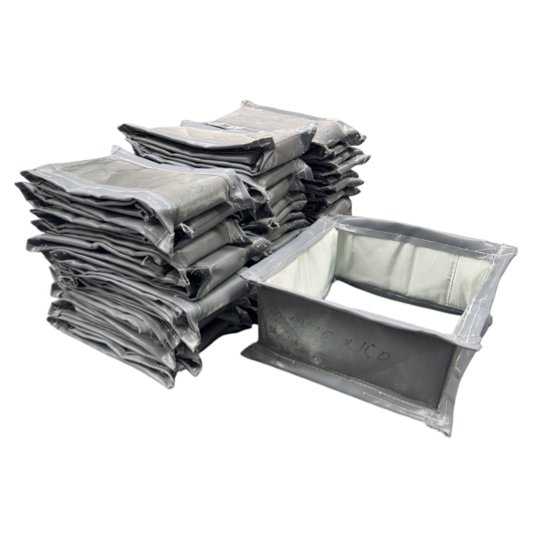
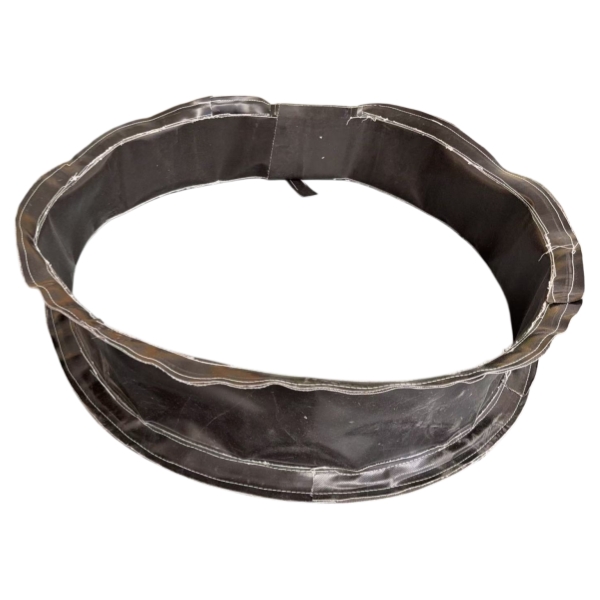
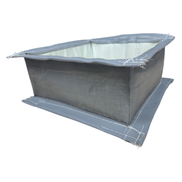
Rectangular joints are widely used on large industrial duct systems. Their corner sections require careful design because the flexible element does not deform identically along straight sides and corners.
Round joints are used on circular ducting, fan connections and exhaust systems. The circumference provides a continuous attachment surface around the duct.
Square configurations are similar in principle to rectangular designs but may be required by specific duct or equipment layouts.
Transitions, non-standard dimensions and application-specific geometries can be manufactured when existing industrial equipment cannot accept a standard shape.
Expansion joint service life depends heavily on correct specification and installation.
Potential failure mechanisms include:
A damaged joint should therefore not automatically be replaced with an identical copy without understanding why the original unit failed.
For replacement projects, operating history can be as valuable as dimensional information.
In industrial ducting, the terms are often used for closely related products. A fabric expansion joint uses a flexible non-metallic fabric or composite element, so it falls within the broader non-metallic expansion joint category. The exact terminology varies by industry and construction.
It provides a flexible connection between sections of industrial ductwork so thermal expansion, contraction, lateral displacement, angular movement, vibration and specified misalignment can be accommodated without making the connection completely rigid.
Typical locations include industrial exhaust ducts, flue-gas systems, furnace and boiler ductwork, fan connections, cement plants, power-generation equipment, steel-processing facilities and air-pollution-control systems.
Yes. Depending on the design, they can accommodate axial compression, axial extension, lateral movement, angular movement and combinations of these movements.
No. Fiberglass is an important reinforcement and high-temperature textile, but complete expansion joints may combine coated fiberglass, PTFE-coated fabric, silicone-coated textiles, silica fabrics, insulation and other materials according to operating conditions.
Tak, gdy cały system materiałowy jest zaprojektowany z uwzględnieniem rzeczywistej temperatury procesu i warunków gazowych. Zastosowania wysokotemperaturowe często wymagają wielu warstw funkcjonalnych i odpowiedniej ochrony między strumieniem gorącego gazu a elastycznym elementem uszczelniającym.
Nie automatycznie. Kompensatory tkaninowe i metalowe charakteryzują się różnymi parametrami ciśnienia, ruchu, temperatury i właściwościami mechanicznymi. Przed zmianą technologii kompensatorów należy ocenić warunki systemu.
Przydatne informacje obejmują szerokość i wysokość kanału lub jego średnicę, długość międzyfazową, wymiary kołnierzy, rozmieszczenie śrub, kształt złącza oraz dostępną przestrzeń montażową. Istotne są również wymagania dotyczące temperatury roboczej, ciśnienia, mediów i ruchu.
BSTFLEX rozwija sięzłącza dylatacyjne z tkaninyDo kanałów przemysłowych, systemów odprowadzania spalin, gorącego powietrza i spalin. Konstrukcja może być dostosowana do kanałów o przekroju okrągłym, prostokątnym, kwadratowym i niestandardowym, a systemy materiałowe dobierane są w zależności od temperatury, ciśnienia, medium procesowego, ruchu i warunków montażu.
Jeśli tworzysz nowy system lub wymieniasz istniejące złącze, zapoznaj się zBSTFLEX Złącze kompensacyjne z tkaniny niemetalowejstrona produktu zawierająca informacje o dostępnych opcjach konstrukcji i personalizacji.
W celu przeprowadzenia oceny technicznej prosimy o przesłanie wymiarów kanału, temperatury normalnej i maksymalnej, ciśnienia roboczego, medium procesowego, ruchu osiowego, ruchu bocznego, długości instalacji, ilości oraz dostępnych rysunków.
Poproś o wycenę niestandardowego złącza kompensacyjnego z tkaniny

 English
 français
 Deutsch
 русский
 italiano
 español
 português
 Nederlands
 العربية
 日本語
日本語 한국의
한국의 Türkçe
 Tiếng Việt
 slovenský
 Indonesia