
Aby zmierzyć niestandardowy mieszek szyty, należy zarejestrować najkrótszą i najdłuższą odległość między tymi samymi dwoma punktami odniesienia montażu, wymaganą przestrzeń wokół chronionego elementu, maksymalną zewnętrzną obwiednię oraz wymiary obu końcówek. W przypadku montażu osiowego, różnica między dwiema zainstalowanymi długościami stanowi wymagany przesuw mieszka.
Skok cylindra lub zdjęcie starej pokrywy to punkt wyjścia, a nie pełna specyfikacja. Przydatny rysunek pokazuje, gdzie mocowany jest miech, ile miejsca pozostaje po złożeniu mechanizmu i ile fałd musi się odsłonić podczas ruchu. Te wymiary dotyczą całego BSTFLEX-a.asortyment miechów szytych na zamówienie, z dodatkowymi szczegółami dotyczącymi konstrukcji okrągłych, prostokątnych, zapinanych na suwak i wspieranych drutem.
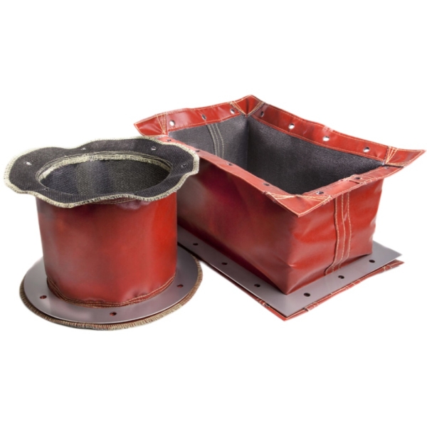
Zidentyfikuj stałe i ruchome punkty mocowania na maszynie. Oznacz je na szkicu jako Koniec A i Koniec B i pokaż dokładne powierzchnie odniesienia użyte do pomiaru długości. Powierzchnia montażowa, ramię kołnierza i krawędź fałdy tkaniny to różne punkty odniesienia; nie należy ich zamieniać.
Zachowaj te same punkty odniesienia na obu końcach przesuwu. Określ również, czy wymiar obejmuje kołnierze, kołnierze lub płyty montażowe, czy też obejmuje tylko elastyczny korpus plisowany. Używaj konsekwentnie milimetrów lub cali i wskaż jednostkę sterującą na rysunkach, które przedstawiają obie jednostki.
Zleć uprawnionemu personelowi ustawienie i zabezpieczenie sprzętu zgodnie z procedurami obsługi i konserwacji. Przed przystąpieniem do pomiarów lub zdjęciem pokrywy należy odizolować niebezpieczne źródło energii, sprawdzić stan bezpieczeństwa i zabezpieczyć komponenty przed niezamierzonym ruchem. Nie dotykać mechanizmu roboczego.
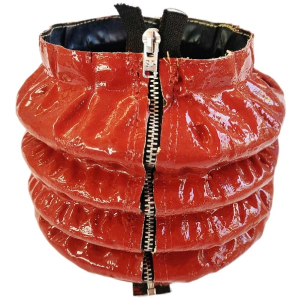
W niniejszym przewodniku Lc i Le opisują wymagane długości montażowe między uzgodnionymi punktami odniesienia. Nie opisują one niezweryfikowanych granic luźnej osłony.
| Wymiar | Co donagrywać | Ważne rozróżnienie |
|---|---|---|
| Długość po skompresowaniu, Lc | Najkrótsza odległość między punktami montażowymi przy wymaganym ruchu maszyny. | Jest to dostępna przestrzeń instalacyjna, a nie możliwość zgniecenia fałd w solidny stos. |
| Wydłużona długość zainstalowana, Le | Największa odległość między tymi samymi punktami mocowania. | Chodzi o wymagany zasięg, a nie długość uzyskaną poprzez naciągnięcie materiału. |
| Wymagany skok miecha, S | Le minus Lc dla instalacji osiowej prostej. | Podróżowanie to nie to samo, co dłuższy dystans. |
| Elastyczna długość ciała | Odległość pomiędzy pierwszym i ostatnim aktywnym fałdem, w miejscu, gdzie jest to potrzebne na rysunku. | Oddziel je od długości zamontowanej i pokaż wszelkie przesunięcia końcowe. |
| Dopuszczalny zakres długości roboczej | Minimalne i maksymalne długości robocze gotowego zespołu zatwierdzone przez producenta. | Rzeczywista instalacja musi przez cały czas trwania ruchu pozostawać w tym zakresie. |
Należy sprawdzić obie zainstalowane pozycje końcowe. Pokrywa może mieć wystarczający zasięg, ale zbyt dużą objętość w stosunku do dostępnej przestrzeni. Z drugiej strony, kompaktowo złożona pokrywa może nie zapewniać wymaganego zasięgu. Nie należy zakładać, że luźna długość stołu lub liczba zagięć rozwiążą którykolwiek z tych problemów.
Mieszek nie powinien stanowić ogranicznika ruchu maszyny. Należy zgłosić wszelkie dodatkowe ruchy, które pokrywa ma obsługiwać, takie jak pozycja konserwacyjna lub zdefiniowany przesuw, i uzyskać potwierdzenie wymaganych naddatków podczas przeglądu projektu.
Rozważmy prostą instalację osiową z najkrótszą odległością montażową wynoszącą 120 mm i najdłuższą odległością montażową wynoszącą 620 mm. W tym przykładowym układzie, stała sekcja końcowa zajmuje 20 mm między każdym punktem mocowania a sąsiednim aktywnym zagięciem.
| Pomiar | Egzaminwartość le |
|---|---|
| Długość po skompresowaniu, Lc | 120 mm |
| Wydłużona długość zainstalowana, Le | 620 mm |
| Wymagany skok miecha, Le - Lc | 620 - 120 = 500 mm |
| Połączone stałe przesunięcia osiowe końcowe | 20 + 20 = 40 mm |
| Elastyczna przestrzeń ciała w pozycji skompresowanej | 120 - 40 = 80 mm |
| Elastyczna długość korpusu w pozycji rozciągniętej | 620 - 40 = 580 mm |
| Zmiana długości elastycznego ciała | 580 - 80 = 500 mm |
Przesuw pozostaje 500 mm, ponieważ z obu pomiarów usunięto te same stałe przesunięcia. Odjęcie ich tylko od jednej długości dałoby błędny wynik. Przesunięcia w tym przykładzie to części pokazane między punktami odniesienia mocowania a aktywnymi fałdami; nie są one automatycznie równe pełnej długości fizycznej nakładającego się kołnierza.
Wartości te ilustrują jedynie metodę pomiaru. Nie są to standardowe wymiary BSTFLEX, zatwierdzony współczynnik kompresji ani dowód na to, że dana konstrukcja jest odpowiednia. Materiał, fałdy, szwy, podpory i mocowania końcowe nadal wymagają wspólnej oceny. W przypadku przesunięcia, ruchu kątowego lub wieloosiowego należy podać ścieżkę ruchu, zamiast polegać wyłącznie na obliczeniach osiowych.
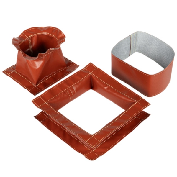
Dlamieszki okrągłe szyte do tłoczysk cylindrów i śrub, zarejestruj największą osłonę elementu, jaką musi otaczać elastyczne ciało. Uwzględnij wszelkie ramiona, nakrętki, złączki i inne elementy znajdujące się w chronionej przestrzeni, zamiast mierzyć tylko pręt lub wał śruby.
Następnie zanotuj maksymalną średnicę zewnętrzną dozwoloną przez otaczające wsporniki, czujniki, węże i osłony. Oznacz wymiary elementów oddzielnie od proponowanych wymiarów miechów, aby producent mógł oszacować luz roboczy, głębokość fałdy i ewentualne wewnętrzne prowadnice.
Otwór korpusu i otwór kołnierza montażowego służą różnym celom. Korpus wymaga odstępu wokół zespołu ruchomego; kołnierz musi pasować do powierzchni mocowania. Zmierz każdą powierzchnię odbiorczą osobno, uwzględniając jej użyteczną długość zaczepienia oraz wszelkie uskoki lub rowki wpływające na zacisk.
Określ, czy zamknięty element obraca się. Osłona wokół obracającej się śruby lub wału wymaga odpowiedniego luzu i układu prowadnic; nie należy zakładać, że będzie się obracać wraz z elementem.
Dlaszyte mieszki prostokątne do torów maszynowych i szyn liniowych, zanotuj wymaganą szerokość i wysokość wewnętrzną, a także maksymalną dostępną szerokość i wysokość zewnętrzną. Pojedynczy pomiar szerokości nie definiuje prostokątnej pokrywy.
Pokaż profile szyn, bloki łożyskowe, wystające śruby, smarowniczki i inne elementy w obrębie obszaru chronionego. Dołącz widok z boku i z boku. Zaznacz, czy pokrywa otacza cały odcinek, czy chroni wybrane boki, i zidentyfikuj otwory, które muszą pozostać dostępne.
Zmierz obie ramy końcowe niezależnie. Nie zakładaj, że ich otwory, wymiary zewnętrzne lub układ otworów montażowych są identyczne. Zwróć uwagę na promienie narożników, przesunięcia i wszelkie przeszkody utrudniające dostęp do elementów złącznych.
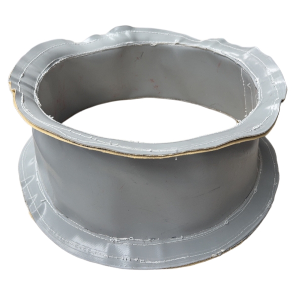
Oznacz poniższe detale jako Koniec A i Koniec B, nawet jeśli okucia wydają się symetryczne. Określ kierunek patrzenia dla każdego szkicu końca, aby nie można było zinterpretować asymetrycznego układu otworów lub położenia zamka odwrotnie.
| Sposób montażu | Wymiary iszczegóły do podania |
|---|---|
| Kołnierz z zaciskiem | Średnica otworu montażowego, użyteczna długość zaczepienia, dostępna przestrzeń na opaskę zaciskową oraz prześwit dla obudowy zacisku. |
| Kołnierz okrągły | Średnica otworu, średnica zewnętrzna, grubość płyty, liczba otworów, średnice otworów oraz średnica okręgu śrub lub współrzędne otworu. |
| Kołnierz prostokątny lub rama | Szerokość i wysokość otworu, wymiary zewnętrzne, grubość, rozmiary otworów i położenie środków na podstawie wyraźnie oznaczonych punktów odniesienia. |
| Mocowanie szczelinowe lub wzmocnione | Szerokość, długość i orientacja szczeliny, umiejscowienie wzmocnienia, szczegóły dotyczące elementów złącznych, dostępność dostępu do instalacji. |
| Łącznik z rozdwojoną końcówką | Pozycja podziału, układ połączeń i sposób montażu złączki wokół istniejącego elementu. |
Należy wyjaśnić, czy elementy montażowe zostaną ponownie użyte, czy dostarczone wraz z nową pokrywą. Zdjęcie z bliska pomoże zidentyfikować układ, ale układ otworów i wymiary połączeń nadal wymagają rysunku wymiarowego lub zweryfikowanych pomiarów.
Podczas określaniazszywane mieszki zapinane na zamek do montażu modernizacyjnego, dodaj pozycję otwarcia wzdłużnego do widoku końcowego. W przypadku okrągłej pokrywy, pozycja zegara jest przydatna tylko wtedy, gdy podany jest również kierunek patrzenia.
Określ dostępną przestrzeń do obsługi suwaka, otwórz osłonę i dotrzyj do końcowych zapięć. Zwróć uwagę na pobliskie osłony, wyloty chłodziwa i gorące powierzchnie, które mogą wpływać na położenie zamknięcia. Zmierz profil roboczy przy zamkniętym zamku błyskawicznym; szerokość otwartej osłony materiałowej nie jest jej wewnętrzną średnicą po zamontowaniu.
Sprawdź mocowania końcowe oraz otwór w materiale. Podłużny zamek błyskawiczny może ułatwić montaż wokół istniejącego elementu, ale jednoczęściowa rama montażowa może nadal wymagać demontażu. Dostęp do instalacji musi zostać oceniony w celu przeprowadzenia pełnego montażu.
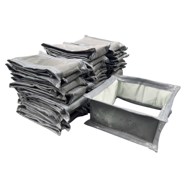
Dlaszyte miechy podparte drutem do zastosowań o dużej średnicy, podaj takie same wymiary wewnętrzne, zewnętrzne, ściśnięte i rozciągnięte, a następnie określ, czy instalacja jest pozioma, pionowa czy pochylona.
W przypadku prac zastępczych należy odnotować istniejący układ podpór i odstępy, tam gdzie są dostępne, oraz określić, czy odstępy te zostały zmierzone przy rozciągniętej, czy ściśniętej pokrywie. Należy dołączyć zdjęcia uszkodzonych podpór, śladów otarć lub ugiętych fragmentów.
Nie należy używać zbrojenia stalowego jako argumentu za pominięciem kontroli prowadzenia. Należy się zastanowić, czy planowana rozpiętość i ruch wymagają oddzielnych prowadnic, zawieszenia lub podpór pośrednich. Należy uwzględnić dostępną przestrzeń na te elementy, zamiast traktować średnicę tkaniny jako całkowitą powierzchnię montażową.
Podaj prędkość ruchu, przyspieszenie (jeśli znane), liczbę cykli na minutę oraz orientację instalacji. Określ normalne warunki otoczenia, narażenie w pobliżu gorących urządzeń, kontakt z chłodziwem lub olejem, pył ścierny i wióry. W przypadku narażenia na ciepło, rozróżnij temperaturę otoczenia, promieniowanie cieplne i ewentualny kontakt z powierzchnią.
Wybrany materiał, powłoka, nić do szycia, zamek błyskawiczny i elementy nośne muszą być dopasowane do danego zastosowania. Wartość temperatury dla samego materiału nie powinna być traktowana jako granica robocza zmontowanego mieszka.
W przypadku instalacji szczelnie zamkniętych lub szybko poruszających się, należy określić, w jaki sposób powietrze może wnikać i wypływać, gdy pokrywa zmienia objętość. Zamiast zakładać, że powietrze będzie wystarczająco przepływać przez szwy lub zamek błyskawiczny, lepiej poprosić o sprawdzenie wentylacji.
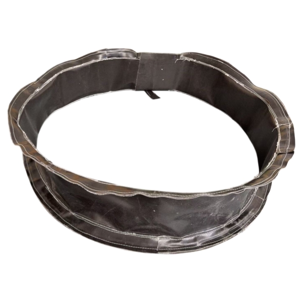
Zachowaj starą pokrywę jako punkt odniesienia dla profilu, okuć, położenia zamknięcia i konstrukcji, ale sprawdź wymagane wymiary na maszynie. Zużyta próbka może być rozciągnięta, odkształcona lub niekompletna. Jej pozorny maksymalny zasięg nie stanowi akceptowalnej długości roboczej.
Sfotografuj oba mocowania, całą instalację oraz wszelkie obszary awarii. Zaznacz oddzielnie wartości zmierzone, wartości na rysunkach i szacunki. Jeśli wymiaru nie można bezpiecznie sprawdzić, oznacz go jako niezweryfikowany, zamiast przedstawiać go jako potwierdzony wymiar produkcyjny.
Nie. Ten sam skok może wystąpić przy różnych odległościach montażowych. Zarówno limity długości montażowej, jak i przekrój poprzeczny oraz końcówki są niezbędne do ustalenia, czy proponowana pokrywa będzie pasować.
Nie można tego wiarygodnie oszacować na podstawie samej liczby zagięć. Grubość materiału, szwy, wzmocnienia, konstrukcja zamknięcia i przejścia między końcami wpływają na złożony pakiet. Należy podać dostępną przestrzeń i poprosić o potwierdzony projekt.
Najpierw prześlij rzeczywiste zmierzone odległości. Określ osobno wszelkie wymagane dodatkowe przesunięcia i uzgodnij je podczas przeglądu projektu. Niewyjaśnione dodatki mogą utrudniać montaż.
Przydatny pakiet ofertowy zawiera zwymiarowany widok z boku, widoki końcowe obu mocowań, zdjęcia instalacji i wymagane warunki pracy. Należy uwzględnić wartości Lc i Le wraz z punktami odniesienia, chronioną obudowę podzespołu, ograniczenia przestrzeni zewnętrznej, szczegóły montażu, dostęp do zamknięcia oraz wszelkie wymagania dotyczące wsparcia.
Proszę podać ilość, określić, czy projekt dotyczy wymiany, czy nowego zespołu OEM, a także wszelkie zmiany rysunku lub wymagania materiałowe. BSTFLEX może dokonać oceny rysunków, wymiarów lub istniejącej próbki w celu przygotowania propozycji mieszków szytych na zamówienie. Przed rozpoczęciem produkcji proszę potwierdzić ostateczne wymiary i konstrukcję na rysunku zatwierdzającym.
Poproś o wycenę mieszków szytych na zamówienieze szczegółami rysunku i aplikacji lub e-mailemsales@pkfiresleeve.com.

 English
 français
 Deutsch
 русский
 italiano
 español
 português
 Nederlands
 العربية
 日本語
日本語 한국의
한국의 Türkçe
 Tiếng Việt
 slovenský
 Indonesia